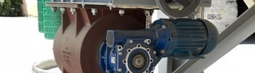
The WAM ILT is a rotary paddle level indicator for detecting a selected high or low material level in silos, bins, and hoppers containing powders or granules. Applications include cement, fly ash, lime, grain, and feed storage, plus other powder-handling systems.
A correct WAM ILT level indicator installation requires a suitable mounting position, free paddle movement, the correct process connection, and model-specific electrical installation.
Important: This guide provides a practical overview, not a substitute for the official WAM installation, operation, and maintenance manual. Follow the manufacturer’s instructions and your facility’s lockout, vessel-entry, and maintenance procedures. Electrical work should be completed by qualified personnel.
How the WAM ILT Level Indicator Works
The WAM ILT-C2 rotary level indicator uses a small motor to rotate a measuring paddle inside the silo or hopper. When the stored material reaches the paddle, it resists and blocks rotation. The indicator’s internal switching mechanism then changes state and sends a point-level signal to an alarm, PLC input, or control circuit.
When the material falls below the paddle and no longer blocks it, rotation resumes and the switch resets. This makes the ILT suitable for detecting whether material is present at one selected location.
The ILT is a point-level indicator. It does not provide a continuous measurement of the quantity or percentage of material throughout the silo.
Why the Correct WAM Coupling Matters
The standard L-shaped paddle is designed to pass through the appropriate WAM process connection. The supplied coupling has a flange-style interface that facilitates installation and removal.
A generic 1-1/2-inch coupling may look similar, but its geometry can make thread engagement or removal more difficult. Depending on the mounting arrangement, the correct WAM coupling may allow the indicator to be removed as a complete assembly without first dismantling the paddle or extension.
Do not treat the WAM coupling as interchangeable with every plumbing fitting. Confirm the model, process connection, paddle, and extension before installation.
Before Installation
Complete this checklist before mounting or wiring the indicator:
- Confirm the correct ILT model and supply voltage for the application.
- Obtain and review the official wiring diagram and manufacturer installation manual.
- Decide whether the device will operate as a high-level or low-level switch.
- Select a location where the paddle can contact material without interference.
- Check for internal braces, filling pipes, aeration equipment, discharge equipment, liners, and other obstructions.
- Verify that the paddle has adequate clearance to rotate.
- Confirm that the process connection matches the indicator and mounting arrangement.
- Isolate and lock out electrical power before work begins.
- Empty, isolate, or otherwise secure the silo according to the facility’s procedures.
Clearance varies by model and vessel. Use the instructions for the specific unit rather than a universal value.
Choosing the Mounting Location
Side mounting
Side mounting can provide high- or low-level detection. Choose a position that represents the intended detection point while accounting for filling patterns and discharge equipment.
Top mounting
Top mounting may use a compatible extension to reach the detection point. The arrangement must follow the manufacturer’s instructions.
Locations to avoid
Avoid the incoming material stream, filling pipe, internal braces, impact zones, and areas prone to buildup. The paddle must rotate freely, and the location must follow WAM instructions and silo-design requirements.
Need Help Selecting a Silo Level Indicator?
MixMaster Components can help you confirm the appropriate model, voltage, mounting arrangement, and application details before ordering.
Step-by-Step WAM ILT-C2 Installation
- Confirm the installation location. Verify the intended detection point and inspect the interior arrangement for material impact, obstructions, and adequate paddle clearance.
- Inspect the WAM coupling and process connection. Check that the coupling, threads, flange interface, paddle, and any extension correspond to the selected ILT model and mounting method.
- Install or verify the mounting coupling. Confirm that the process connection is correctly positioned and installed in accordance with the silo design and manufacturer instructions.
- Insert the paddle assembly carefully. Guide the L-shaped paddle or approved extension through the process connection without forcing or bending it.
- Secure the indicator. Attach the assembly using the manufacturer’s specified method. Do not improvise tightening values or alter the process connection.
- Orient the housing and cable entry. Position them as directed so wiring can be routed appropriately and environmental sealing can be maintained.
- Complete the electrical wiring. A qualified person should confirm the supply voltage and wire the device using the official diagram for the exact model. Do not rely on assumed terminal assignments.
- Restore power and perform a functional test. Follow the manufacturer’s test procedure and facility safety controls.
- Verify the receiving signal. Confirm that the alarm, PLC input, or plant control panel changes state as intended and is assigned to the correct function.
- Record the installation. Document the model, voltage, location, mounting arrangement, wiring verification, and test result for future maintenance.
Testing After Installation
Before normal filling, verify that the paddle rotates freely. Using the official procedure, confirm that the switch changes state when rotation is blocked and resets when released.
Confirm the corresponding alarm, PLC input, or control-panel indication responds as intended. Follow the manufacturer manual and plant safety procedures.
Common Installation Mistakes
- Using the wrong coupling or process connection.
- Installing the paddle directly in the material inlet stream.
- Wiring the device without using the model-specific diagram.
- Failing to confirm the required supply voltage.
- Leaving insufficient clearance around the paddle.
- Mounting near an internal brace, filling pipe, or other obstruction.
- Treating a point-level switch as a continuous level sensor.
- Failing to function-test the alarm or PLC input before startup.
- Allowing material buildup to restrict paddle movement.
- Ignoring the manufacturer’s environmental sealing requirements.
WAM ILT Troubleshooting Guide
| Problem | Possible Cause | Recommended Check |
|---|---|---|
| Paddle does not rotate | Material contact, buildup, obstruction, loss of power, or an internal fault | Isolate the equipment; check clearance, buildup, supply, and the manual’s diagnostic procedure. |
| Indicator does not send a signal | Incorrect wiring, wrong voltage, loose connection, or switching fault | Have qualified personnel compare wiring and voltage with the official diagram and test the receiving circuit. |
| False high-level alarm | Buildup, direct material impact, or restricted paddle movement | Inspect paddle condition, mounting location, clearance, and buildup. |
| Alarm does not reset | Material remains at the paddle, buildup persists, or the signal circuit has a fault | Confirm the material level, safely clean the paddle, and test switch and control-panel states. |
| Frequent material buildup | Mounting in a buildup zone or unsuitable application conditions | Review the location, material behavior, mounting arrangement, and manufacturer guidance. |
| Intermittent electrical signal | Loose termination, cable issue, moisture ingress, or unstable supply | Have qualified personnel inspect connections, cable glands, enclosure condition, and supply. |
| Difficulty removing the indicator | Incorrect coupling, thread engagement problem, or buildup | Verify the process connection and WAM coupling; do not force the assembly. |
| Paddle or extension appears damaged | Material impact, obstruction, or unsuitable mounting | Remove the unit safely, inspect components, and confirm the location before replacement. |
Preventive Maintenance Checklist
- Visually inspect the housing for damage or deterioration.
- Check cable glands and electrical connections.
- Verify the mounting hardware and process connection.
- Inspect the paddle and extension for wear, bending, or damage.
- Remove material buildup using an approved safe procedure.
- Test the switching function.
- Verify the corresponding alarm or PLC input.
- Confirm the indicator remains protected from direct material impact.
- Record inspection findings and corrective work.
Maintenance frequency should follow the manufacturer’s guidance, the plant’s preventive-maintenance program, operating conditions, and the behavior of the stored material.
Related Silo Components
Related equipment includes silo pressure relief valves, silo vent dust collectors, and bin aerators.
Frequently Asked Questions
Can a WAM ILT be installed on the side of a cement silo?
Yes. The product is used in side- or top-mounted arrangements, provided the specific model, process connection, mounting location, and paddle clearance follow WAM instructions and the silo design.
Can it be used as both a high-level and low-level indicator?
The ILT can be applied at a selected high or low detection point. The mounting position and control logic must be designed for the intended function.
Why should the original WAM coupling be used?
The appropriate WAM coupling is designed to accept the paddle and provide the intended flange-style interface. It can simplify installation and may allow removal as a complete assembly.
What materials can a rotary paddle indicator detect?
Rotary paddle indicators are commonly used with powders and granular materials, including cement, fly ash, lime, grain, and feed. Confirm suitability for the specific material and operating conditions.
Is the ILT a continuous level sensor?
No. The ILT detects material at one selected point. It does not continuously measure the amount or percentage of material in the vessel.
Get Help with Your Level-Detection Application
Need help selecting or replacing a rotary level indicator for a cement silo, hopper, or bulk-storage application? Contact MixMaster Components with your material, silo configuration, required voltage, mounting position, and application details. Our team can help identify the appropriate component and provide availability and shipping information.